
Prior to the NES, most controllers had a joystick and one or two buttons. The Atari joystick was wired in parallel, where one wire corresponded to one button, and pressing a direction or a button completed a circuit with the common (ground wire). The program would read these button presses in parallel, where reading from a single memory location would give the state of each of the five buttons at one time.
Nintendo's controllers were to come with a D-pad and four buttons. These were originally hard-wired in the Famicom but would have required at least nine wires if wired by the traditional parallel standard. Moreover, if they wanted to use other kinds of peripherals, they may have found that difficult. To cut down on wires, Nintendo decided to use a serial method for reading buttons. This also allowed for more varied expansion, as will be discussed below.
In each NES and Famicom controller, there is a shift register. This shift register is clocked by the CPU clock. When activated with a write signal from the CPU, the shift register will send the state of each button pressed one button at a time in the interval of a clock pulse. The CPU must read a single bit from a memory location eight times to determine the state of each button on the controller in the following order: A, B, Select, Start, Up, Down, Left, Right.
For the Famicom, memory addresses $4016 and $4017 were assigned to read to peripherals. Button states from Controller I would be read on $4016 Data Bit 0 (D0) and Controller II would be read on $4017 D0. On the Famicom, $4016 D0-D2 and $4017 D0-D4 were readable. The Famicom had two hardwired controllers, and the start and select buttons did not exist on Controller II. The shift register always sent out a not pressed signal for those buttons in their shifted order. There was a microphone included on Controller II and its output is read by the CPU on $4016 D2. Note that $4016 is used, not $4017.
The Famicom has a 15-pin Expansion Port. On this port, there are pins for $4016 D1 and $4017 D0-D4. You could plug in 3rd party controllers and they would use $4016 D1 for Controller I's input. This worked for most games, but not all of them. Although $4017 D0 was available on the Expansion Port, it was always used by the hard-wired Controller II, so a game would have to support reading $4017 D1 for the second player. Eventually, three and four player games would use these assignments for Controller 3 and 4, respectively. When it came to expansion devices, the Famicom Gun uses $4017 D3 & D4.
The front loading NES has a pair of detachable controllers and a unique 7-pin controller port. On Controller Port 1, there were pins for $4016 D0, D3 & D4. On Controller Port 2, there were pins for $4107 D0, D3 & D4. NES controllers use their respective D0 pin for compatibility with Famicom games. The NES Zapper is compatible with the Famicom Gun in that all games expect its input on $4017 D3 & D4. However, $4016 D3 & D4 is available for a second Zapper. The unlicensed games Baby Boomer and Chiller support a Zapper in Controller Port 1. This is not possible on any Famicom (Famicom, AV Famicom, Twin Famicom etc.)
The NES also had a 48-pin Expansion Port on the underside of its enclosure which was never officially used. Pins for $4016 D0-D4 and $4017 D0-D4 are present. There are more pins present than on the Famicom Expansion Port. The physical shape and recessed nature of the Port makes these pins difficult to get to unless you have an ENIO board, which is a product of the 21st century. The NES Expansion Port was never used during the NES's official lifetime. It has a plastic cover which must be removed with a sharp knife or small saw.
Because the Expansion Port had to be used on the Famicom and was never used on the NES, similar NES and Famicom peripherals are usually functionally incompatible. Thus the NES Four Player Adapters, the Four Score and Satellite, are incompatible with the 3-4 player adapters for the Famicom. Ditto for the Arkanoid Controller, the Power Pad/Family Trainer Mat. They either use different data bits or different ways of reading from these controllers. This makes Japanese games that use these peripherals incompatible with U.S. peripherals and vice versa.
The Top Loading NES eliminated the NES Expansion Port but retained the D3-D4 connections on Controller Ports 1 & 2. The AV Famicom uses standard NES controller ports, eliminating the Controller II microphone. The AV Famicom does not connect the pins on Controller Ports 1 & 2 which would correspond to D3-D4, but as for Controller Port 2 you can simply route the signals with a pair of wires soldered to the Famicom Expansion Port. It is a simple mod.
Inside the Famicom, front loading and top loading NESs are a pair of hex inverter chips (40HC368s). Each hex inverter chip provides six inverters. $4016 is assigned to the first inverter chip and each data bit gets one of the inverters. $4017 is assigned to the second inverter chip and each data bit gets one of the inverters. The remainder of the inverters are assigned to other functions or grounded. These inverters are special tri-state inverters because they only allow peripherals access to the data bus when $4016 or $4017 is being accessed, not when any other memory address is being accessed. This prevents peripheral data from conflicting with ROM or RAM data.
On the AV Famicom, a custom Nintendo chip initially marked as BU3266 and later marked BU3270 provides all the inverters for the system. This chip has nine inverters, exactly the number needed for the AV Famicom to implement all the functions it needs. In order to implement the microphone function on an AV Famicom, you need another tri-state inverter.
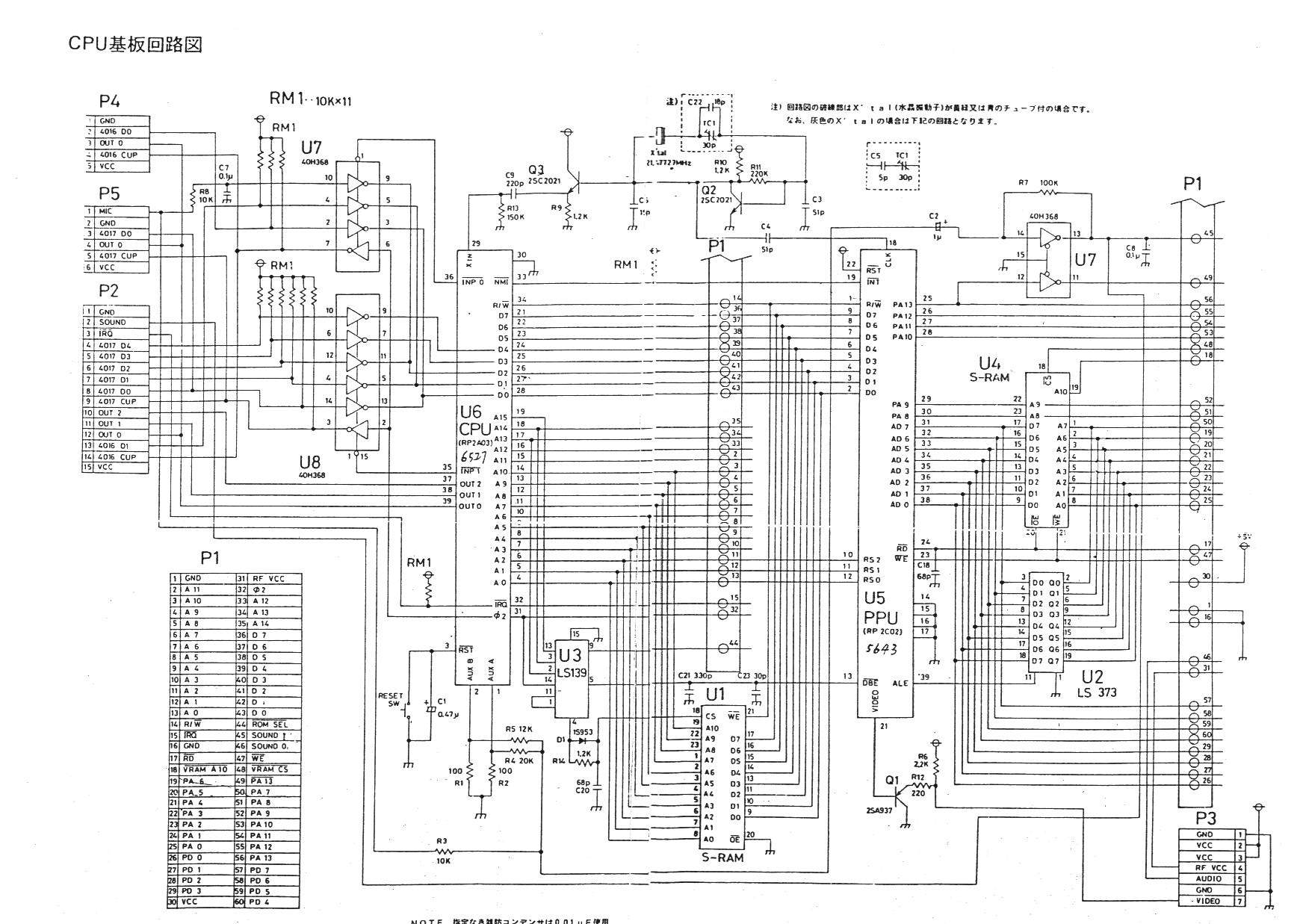
In theory, you can mod an AV Famicom to accept microphone input. The official Famicom Schematic can be found here : http://nesdev.com/Ntd_8bit.jpg As we can see, the Mic line goes through a 10K resistor, then a 0.1uF ceramic capacitor, then to an inverter input on a 40HC368. From the 368's output it then goes directly to the CPU's D2 pin. You need to add a 368 into the AV Famicom. Wire the 368 as follows :
368 Pin 1 to CPU Pin 36
368 Pin 2 to Mic Input (after the 10K resistor and 0.1uF capacitor)
386 Pin 3 to CPU Pin 26
386 Pins 4, 6, 10, 12 & 14 to +5v or GND (unused inverter inputs should not be left floating)
386 Pin 8 to GND
386 Pins 15 & 16 to +5v.
If you want to make the mod canonical, which outputs your voice to the TV speaker, run another line from the microphone, through another 10K resistor, to the area just past the mixing stage as shown on the Famicom schematic. The AV Famicom uses the same four resistors to mix the two CPU audio pins.
I have NOT tested this mod and do not know if it will work. I take no responsibility if you destroy your AV Famicom, you attempt it at your own risk. The Famicom's microphone is a electret microphone, but I am not sufficiently apprised on specifications to know if another kind of microphone would work. You need to use a Famicom Controller II, but you only need to connect the +5v, GND and Mic In line for the Microphone function. The fifth schematic on this page shows how it is implemented in the Famicom Controller II : http://www43.tok2.com/home/cmpslv/Famic/Famic.htm
Thank you for continuing by to look into this. I've had your post linked on nesdev for a long time hoping for an update. I tried and failed to hack a famicom ii controller to use with the enio board on the nes. I'd love to see someone actually modify the av famicom with the extra chip from a donor.
ReplyDeleteYou shouldn't need a donor for the chip, its an off the shelf simple TTL logic chip.
ReplyDeleteVery cool mod for microphone restoration. If I get an AV Famicom at some point I will need to try this. Related to that, what pins would I need to connect to enable $4016 D3 and D4 in an original Famicom? Would I be able to use the same added inverter chip, or can I bum some connections from one already in the system?
ReplyDeleteYou could take D3 and D4 from the custom Nintendo chip, piggyback a tri-state inverter and connect the output enable to the $4016 which the custom chip also uses. I haven't tried it.
ReplyDeleteAh I see thank you. From what you've described I have to assume this would only work on the AV Famicom?
ReplyDeleteDo you know if the microphone of Famicom controller II can work on NES front loader?
ReplyDeleteIt very much will not. There is no microphone input on any western model.
Delete